Showing posts with label Mechanical. Show all posts

DIFFERENT TYPES OF AUGER/SCREW CONVEYOR AND THEIR APPLICATIONS


A screw conveyor or auger conveyor is a mechanism that uses a rotating helical screw blade, called a "flighting", usually within a tube, to move liquid or granular materials. They are used in many bulk handling industries. Screw conveyors in modern industry are often used horizontally or at a slight incline as an efficient way to move semi-solid materials, including food waste, wood chips, aggregates, cereal grains, animal feed, boiler ash, meat and bone meal, municipal solid waste, and many others. The first type of screw conveyor was the Archimedes' screw, used since ancient times to pump irrigation water[1]


STANDARD SECTIONALSCREW: Most common. Used to convey a wide variety of products.


RIBBON FLIGHT SCREW: Used for conveying sticky, gummy or viscous substances, or where the material tends to stick to the flighting at the pipe. Available in integral style (as shown) or post style ribbon.


CUT FLIGHT SCREW: Used for conveying light, fine, granular or flaky materials.  Also used for mixing material in transit or for removing grit and dirt from the grain, cottonseed, etc.


CUT AND FOLDED FLIGHT SCREW: Used to create a lifting motion with the material that promotes agitation and aeration while mixing.


SECTIONAL FLIGHT SCREW WITH PADDLES: Used to mix material while being conveyed. Paddles may be fixed (welded in place) or adjustable pitch (bolt mounted, to provide different degrees of mixing).


PADDLE SCREW: Used for complete mixing or stirring material. Paddles may be fixed (welded in place) or adjustable pitch (bolt mounted, to provide variable degrees of mixing).


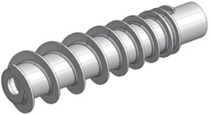
SHORT PITCH SCREW: Used primarily in incline or hopper fed applications where the pitch is less than the diameter of the screw.

INTERRUPTED FLIGHT SCREW: As with a “ribbon screw”, used for conveying sticky, gummy or viscous substances, or where the material tends to stick to the flighting at the pipe; but offers better throughput and flow consistency than a ribbon screw.


CONE SCREW: Used to provide better “mass flow” (uniform discharge) from a hopper or bin above than screws with variable pitch alone.

 SHAFTLESS SCREW: Similar to ribbon screws, used for conveying sticky, gummy or viscous substances, or where the material tends to stick to the flighting at the pipe. Also used with stringy products that would typically wrap around the screw pipe.


PRESS SCREW: Typically surrounded by screens and used to press moisture from various products

Note:
All items included may not be reproduced in any form without written permission from CEMC

Share:

SCREW CONVEYOR COMPONENTS AND DESIGN


1.    Screw
2.    Drive Shaft
3.    Intermediate Shaft
4.    End Shaft
5.    Covers
6.    Hanger
7.    Hanger Bearing
8.    Discharge
9.    Saddle
10.   End Bearings
11.   Shaft Seal
12.   End Plates
13.   Internal Collars/Bushings
14.   Coupling Bolts
15.   Bolt Pads
16.   Cover Clamps
17.   Inlet
18.   Troughs


SCREW DIA B SHAFT DIA C LENGTH D LENGTH WT** E F BOLT G H J K L M N P Q
6 1 1/2 9'-10" 10'0" 400 1     3/8 6 2 4 1/2 5 5/8 5 7 8  1/8 1 1/2 13 1/4
9 1 1/2 9'-10" 10'0" 650 1 1/2  1/2 8 2 6 1/8 7 7/8 7 1/8 10 9 3/8 1 5/8 17 1/8
9 2 9'-10" 10'0" 675 1 1/2  1/2 8 2 6 1/8 7 7/8 7 1/8 10 9 3/8 1 5/8 17 1/8
10 1 1/2 9'-10" 10'0" 700 1 3/4  1/2 9 2 6 3/8 8 7/8 7 7/8 11 9 1/2 1 3/4 18 3/8
10 2 9'-10" 10'0" 730 1 3/4  1/2 9 2 6 3/8 8 7/8 7 7/8 11 9 1/2 1 3/4 18 3/8
12 2 11'-10" 12'0" 1050 1 5/8  5/8 10 1/2 2 7 3/4 9 5/8 8 7/8 13 12 1/4 2 20 1/2
12 2  7/16 11'-9" 12'0" 1080 1 5/8  5/8 10 1/2 3 7 3/4 9 5/8 8 7/8 13 12 1/4 2 20 1/2
12 3 11'-9" 12'0" 1140 1 5/8  5/8 10 1/2 3 7 3/4 9 5/8 8 7/8 13 12 1/4 2 20 1/2
14 2  7/16 11'-9" 12'0" 1240 1 5/8  5/8 11 1/2 3 9 1/4 10 7/8 10 1/8 15 13 1/2 2 23 1/4
14 3 11'-9" 12'0" 1300 1 5/8  5/8 11 1/2 3 9 1/4 10 7/8 10 1/8 15 13 1/2 2 23 1/4
16 3 11'-9" 12'0" 1520 2     5/8 13 1/2 3 10 5/8 12 11 1/8 17 14 7/8 2 1/2 25 3/4
18 3 11'-9" 12'0" 1790 2     5/8 14 1/2 3 12 1/8 13 3/8 12 3/8 19 16 2 1/2 28 5/8
18 3  7/16 11'-8" 12'0" 1900 2     5/8 14 1/2 4 12 1/8 13 3/8 12 3/8 19 16 2 1/2 28 5/8
20 3      11'-9" 12'0" 1960 2 1/4  3/4 15 1/2 3 13 1/2 15 13 3/8 21 19 1/4 2 1/2 31 5/8
20 3  7/16 11'-8" 12'0" 2050 2 1/4  3/4 15 1/2 4 13 1/2 15 13 3/8 21 19 1/4 2 1/2 31 5/8
24 3  7/16 11'-8" 12'0" 2510 2 1/2  3/4 17 1/2 4 16 1/2 18 1/8 15 3/8 25 20 2 1/2 37 3/4
24 3 15/16 11'-8" 12'0" 2620 2 1/2  3/4 17 1/2 4 16 1/2 18 1/8 15 3/8 25 20 2 1/2 37 3/4
30 3  7/16 11'-8" 12'0" 3150 2 3/4  3/4 21 4 19 3/4 21 1/2 18 3/8 31 24 2 1/2 44 3/8
30 3 15/16 11'-8" 12'0" 3260 2 3/4  3/4 21 4 19 3/4 21 1/2 18 3/8 31 24 2 1/2 44 3/8
36 3 15/16 11'-8" 12'0" 4160 2 3/4 1 25 4 24 26 23 37 * 2 1/2 54 1/8
36*** 4  7/16 11'-7" 12'0" 4275 2 3/4 1 25 5 24 26 23 37 * 2 1/2 54 1/8

*Has 4 Bolts
**Wt. of one complete stainless steel conveyor with U-trough, medium flight thickness, “D” length, CSW seals, flange bearings less drive.
***Sizes larger than 36” are available. Contact Conveyor Eng. & Mfg. for more information.

Note:
All items included may not be reproduced in any form without written permission from CEMC
Share:

Tekanan Kerja Pipa ASTM A53 Seamless/Welded Sch 40


Mampukah Pipa ASTM A53 Gr. B Seamless Sch 40 diameter 2 Inch menahan tekanan uap sebesar 3 Bar yang umum diaplikasikan pada Pipa Steam Coil Storage Tank Minyak Sawit?

Atau, Mampukah Pipa ASTM A53 Gr. A Welded Sch 40 diameter 2 Inch menahan tekanan uap sebesar 3 Bar tersebut?

Jawabannya adalah sangat mampu.

Pertama, Sertifikat pabrikan menunjukan hasil "Good" pada uji Hydrotest tekanan 2300 psi atau setara dengan 159 BAR.


Kedua, hasil perhitungan dengan menggunakan persamaan Barlow adalah 2430 psi atau setara dengan 168 BAR.

Berikut ini adalah penjelasan tentang persamaan Barlow tersebut.

Maaf penjelasannya di bawah ini menggunakan bahasa Inggris. ini dilakukan untuk menghindari kesalahan translate pada variable-variable yang diketahui.


Working Pressure / Maximum Allowable Pressure


1) Working pressure is a term used to describe the maximum allowable pressure a pipe may be subjected to while in-service. Barlow's formula can be used to calculate the maximum allowable pressure by using design factors as:


*1 psi (lb/in2) = 6,894.8 Pa (N/m2) = 6.895x10⁻² bar 


1.  2) Temperature derating factors  of steel pipes due to stress are indicated below:
Temperature
Temperature Derating Factor
(oF)
(oC)
< 250
< 121
1.00
250 - 300
121 - 149
0.97
300 - 350
149 - 177
0.93
350 - 400
177 - 204
0.90
400 - 450
204 - 233
0.87


2.  1) The strength of a material is determined by the tension test which measure the tension force and the deformation of the test specimen.

a.      the stress which gives a permanent deformation of 0.2% is called the yield strength

b. The stress which gives rupture is called the ultimate strength or the tensile strength


Typical strength of some common materials:
Material
Yield Strength
(psi)
Ultimate (Tensile) Strength
(psi)
Stainless Steel, 304
30000
75000
6 Moly, S31254
45000
98000
Duplex, S31803
65000
90000
Nickel, N02200
15000
55000
A53 Seamless and Welded Standard Pipe, Grade A
30000
48000
A53 Seamless and Welded Standard Pipe, Grade B
35000
60000


3.  3) Longitudinal joint factor ( ) for steel Pipe

The longitudinal joint factor to be used in the design formula in § 192.105 is determined in accordance with the following table:
Specification
Pipe class
Longitudinal joint factor (E)
ASTM A 53/A53M
Seamless
1.00
Electric resistance welded
1.00
Furnace butt welded
.60
ASTM A 106
Seamless
1.00
ASTM A 333/A 333M
Seamless
1.00
Electric resistance welded
1.00
ASTM A 381
Double submerged arc welded
1.00
ASTM A 671
Electric-fusion-welded
1.00
ASTM A 672
Electric-fusion-welded
1.00
ASTM A 691
Electric-fusion-welded
1.00
API Spec 5L
Seamless
1.00
Electric resistance welded
1.00
Electric flash welded
1.00
Submerged arc welded
1.00
Furnace butt welded
.60
Other
Pipe over 4 inches (102 millimeters)
.80
Other
Pipe 4 inches (102 millimeters) or less
.60


4.  4) Design factor ( ) for steel pipe.

(a) Except as otherwise provided in paragraphs (b), (c), and of this section, the design factor to be used in the design formula in § 192.105 is determined in accordance with the following table:
Class location
Design factor (F)
1
0.72
2
0.60
3
0.50
4
0.40


(b) A design factor of 0.60 or less must be used in the design formula in § 192.105 for steel pipe in Class 1 locations that:
(1) Crosses the right-of-way of an unimproved public road, without a casing;

(2) Crosses without a casing, or makes a parallel encroachment on, the right-of-way of either a hard surfaced road, a highway, a public street, or a railroad;

(3) Is supported by a vehicular, pedestrian, railroad, or pipeline bridge; or

(4) Is used in a fabricated assembly, (including separators, mainline valve assemblies, cross-connections, and river crossing headers) or is used within five pipe diameters in any direction from the last fitting of a fabricated assembly, other than a transition piece or an elbow used in place of a pipe bend which is not associated with a fabricated assembly.
(c) For Class 2 locations, a design factor of 0.50, or less, must be used in the design formula in § 192.105 for uncased steel pipe that crosses the right-of-way of a hard surfaced road, a highway, a public street, or a railroad.
(d) For Class 1 and Class 2 locations, a design factor of 0.50, or less, must be used in the design formula in § 192.105 for -
(1) Steel pipe in a compressor station, regulating station, or measuring station; and
(2) Steel pipe, including a pipe riser, on a platform located offshore or in inland navigable waters.


Reference:
1)    “Calculate pipes internal, allowable and bursting pressure”, November 9th 2016, http://www.engineeringtoolbox.com/barlow-d_1003.html.
2)    “Temperature derating factor for steel pipes”, November 9th 2016,http://www.engineeringtoolbox.com/temperature-derating-factor-steel-pipes-d_1744.html.
3)    “49 CFR 192.113 - Longitudinal joint factor (E) for steel pipe”, November 9th 2016, https://www.law.cornell.edu/cfr/text/49/192.113.
“49 CFR 192.111 - Design factor ( F ) for steel pipe”, November 9th 2016, https://www.law.cornell.edu/cfr/text/49/192.111.
Share:

Popular Posts

Followers

Labels

Blog Archive

Recent Posts